


Our company have three kinds harmonic driver models, which are defined by the design of gear tooth separately.
We found that harmonic meshing is based on the geometric mapping theory of curve (curved surface) by researching. In addition to applying in harmonic reducer, it can also be applied in high rigid RH reducer for the purpose of precise control. Traditional theory is established according to Willis theorem. On the basis of this theory , the conjugate tooth shape is deduced. However, harmonic meshing is comparatively special, in fact, it is not conjugate. Our theory is optimized from traditional theory, so that meshing application scope is much broader and it is more suitable for harmonic meshing.
For suitable for different usage and cost level market needs, we kept model as below for customers’ choice.
Using “U” Type gear design, international size model.
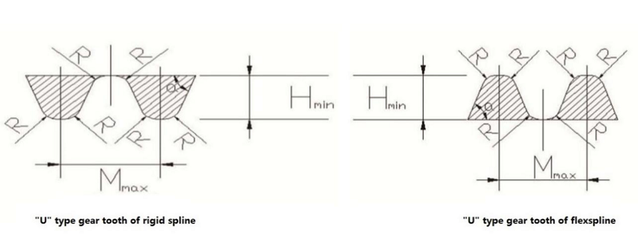
After Shape comparison of “U” type tooth and tooth of similar involute tooth products, the strong points of “U” type tooth are prominent
► Tooth height is low and relatively bigger meshing capacity can be obtained without necessary deep meshing distance.
► Relatively wide tooth width, increased tooth base arc can reduce the risk of fracture failure.
► Life span of flexspline can be greatly improved owing to low necessary deformation of flexspline.
► Up to 20%~30% of teeth are involved in meshing, so that specific pressure on tooth surface is comparatively low.
“U” model harmonic drivers have four basic model, which are classified according to shape & length of flexspline. Also, each basic model includes several drive ratios too.
Below is the identity rules of “U” type drivers:
| Product Model | Structure Form | Characteristic | Technology Capability | Model Reference |
| CCD-U | Cup-type&dwarf flexspine | Dwarf cup flexspine, thinner than standard |
Model no: 14-50 Trans. Ratio:50-160 |
The best choice, except need high torque |
| CCS(H)-U | Cup-type&standard flexspine (H-high torque) | Standard cup flexspine,with high torque modle choice |
Model no: 14-50 Trans. Ratio:30-160 |
Scope of ratio bigger, also with high torque design |
| CHD-U | Hollow&dwarf flexspine | Dwarf flexspine, thinner than standard |
Model no: 14-50 Trans. Ratio:50-160 |
The best choice, except need high torque |
| CHS(H)-U | Hollow&standard flexspine(H-high torque) | Hollow flexspine,with high torque modle choice |
Model no: 14-50 Trans. Ratio:30-160 |
Scope of ratio bigger, also with high torque design |
“U” model identify from 6 parts of products:
CHS(H) - U - 14 - 50 - C - Ⅰ
① ② ③ ④ ⑤ ⑥
① C----- China harmonic drive H----- Hollow shape flexspine
C----- Cup shape flexspine S----- Standard length flexspine
D----- Dwarf flexspine (H)----- High torque, if not is standard torque
D----- Dwarf flexspine (H)----- High torque, if not is standard torque
② U----- “U” tooth
③ 14---- Specification code (model example)
Specification code corresponds to pitch diameter as below table:
| Specification code | 14 | 17 | 20 | 25 | 32 | 40 | 50 | 58 |
| Pitch diameter(mm) |
35.6 |
43.2 | 50.8 | 63.5 | 81.3 | 102 | 127 | 147 |
④ 50---- Reduction ratio
Ratio scope from 30.50.80.100.120.160, customized demand can be meet too.
⑤ C----- Complete type drive
P----- Parts component type drive
CL----- Light weight complete drive
⑥ Ⅰ----- Connection form, standard type, input bearing matches up with internal hole of cam through the connection of flat key.
Ⅱ----- Connection form, crossing slipper type coupling, input bearings is connected with cam by means of cross slipper coupling
Ⅲ----- Connection form, hollow cylinder type, input bearing is connected with hollow cam through the connection of bolts
Ⅳ----- Connection form, shaft input type.


