


1Criteria:
Installation notes
1. All components must be cleaned prior to assembling.2. In assembling, slide the wave generator into the open-end of the flexspline first. With the flexspline’s bottom forward, mounting the flexspline with wave generator into the circular spline while turning the wave generator to facilitate mounting.
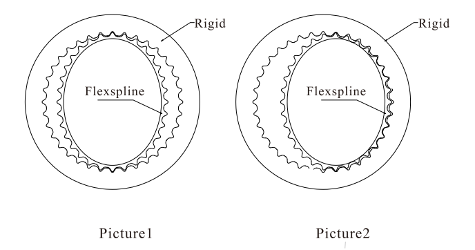
3. After cam installation, please make sure the meshing between flexspline and rigid is symmetric at the position 180 degree. (Picture 1) It will cause vibration and damage if leaning towards one-side. (Picture 2)
4. After assembling, the input shaft must not have any axial play, otherwise the bottom of the flexspline maybe damaged somewhere.
5. The detailed requiements and the positional-tolerances are the same for the assembly components as well as for the complete reducers.
6. Before assembling, all surface of every element inside the assembly should be pre-lubricated with lubricating oils or semifluid grease. After assembling, some lubricant should remain in the wave generator, the spline’s teeth, the external surfaces of the flexible ball bearing and the internal surface of the flexspline.
7. The pine holes in the output shaft are located by the two holes on the bottom flange of the flexspline and drilled after the flexspline has been mounted on the shaft, then dowel pins are mounted.
8. The outside diameter of the clamp ring inside the flexspline should be smaller than the outside diameter of the flexspline’s bottom flange. The contacting outer periphery of the clamp ring should be rounded with the radius specified, to protect the flexspline’s bottom-diaphragm from damage.
-

Tel: +86-21-20965251
Fax: +86-21-33250281www.chinaharmonicdrive.com
sales@chinaharmonicdrive.com -
Company
-
Products
-
Contact
Copyright Right © China Trans-tech Co.,Ltd
Follow us:


